
Advanced Injection Molding, Ultra-Precision Tooling and High-Performance Materials for Silicon Photonics & Optical Interconnects
Engineering insight · October 2026 · Ming-Li Precision Steel Molds Co., Ltd.
Artificial intelligence (AI) infrastructure is pushing networking systems toward greater bandwidth density, lower energy consumption and more demanding thermal environments. Co-packaged optics (CPO) is one of the technologies reshaping this landscape by bringing optical engines close to high-performance switching silicon. It also creates a less visible—but important—engineering challenge: how to manufacture the mechanical, insulating, retention and cable-management components that allow advanced optical assemblies to be assembled consistently.
For optical communications engineers and sourcing teams searching for a CPO precision injection molding supplier, the right manufacturing partner needs more than a molding press. Reliable polymer components often require coordinated material selection, mold design, micro-feature machining, dimensional metrology, assembly review and disciplined process control.
Ming-Li Precision, based in Taichung, Taiwan, offers precision mold design and manufacturing, engineering-polymer injection molding, micro molding, insert molding, ultra-precision machining and inspection services. We welcome CPO-related, silicon photonics and optical-interconnect RFQs for application-specific polymer components and tooling. Each proposed component is reviewed against its actual performance and qualification requirements; CPO platform certification or prior production is not implied.
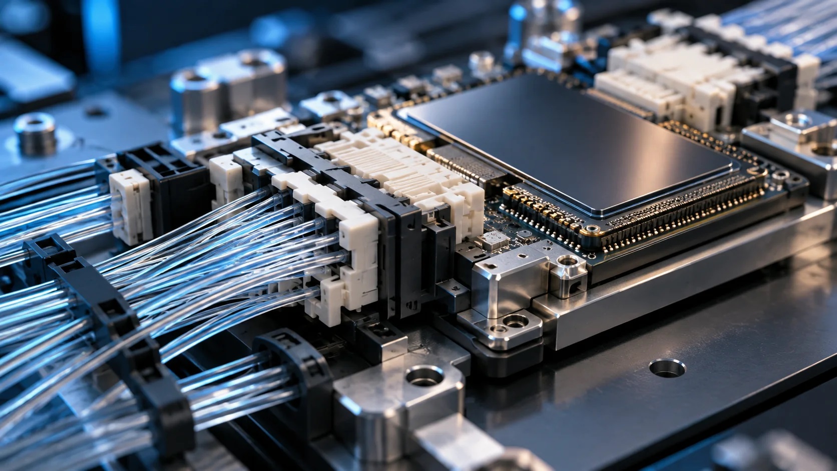
Conceptual visualization of optical-interconnect hardware and precision polymer connector structures; not a photograph of a Ming-Li customer product or qualified CPO assembly.
1. What Is Co-Packaged Optics—and Why Do Mechanical Components Matter?
In a conventional network switch, electrical signals travel from the switching ASIC through board-level interconnects to pluggable optical transceivers located at the equipment faceplate. As bandwidth rises, the electrical path can impose increasingly difficult signal-integrity and power challenges.
CPO reduces the electrical distance by placing optical engines very close to the switch ASIC, typically in an integrated package-level or adjacent architecture. Fiber paths then carry optical signals out of the system. Approaches vary significantly between platforms: external laser sources, detachable fiber connectors, optical engine integration, cooling and serviceability are not identical across suppliers.
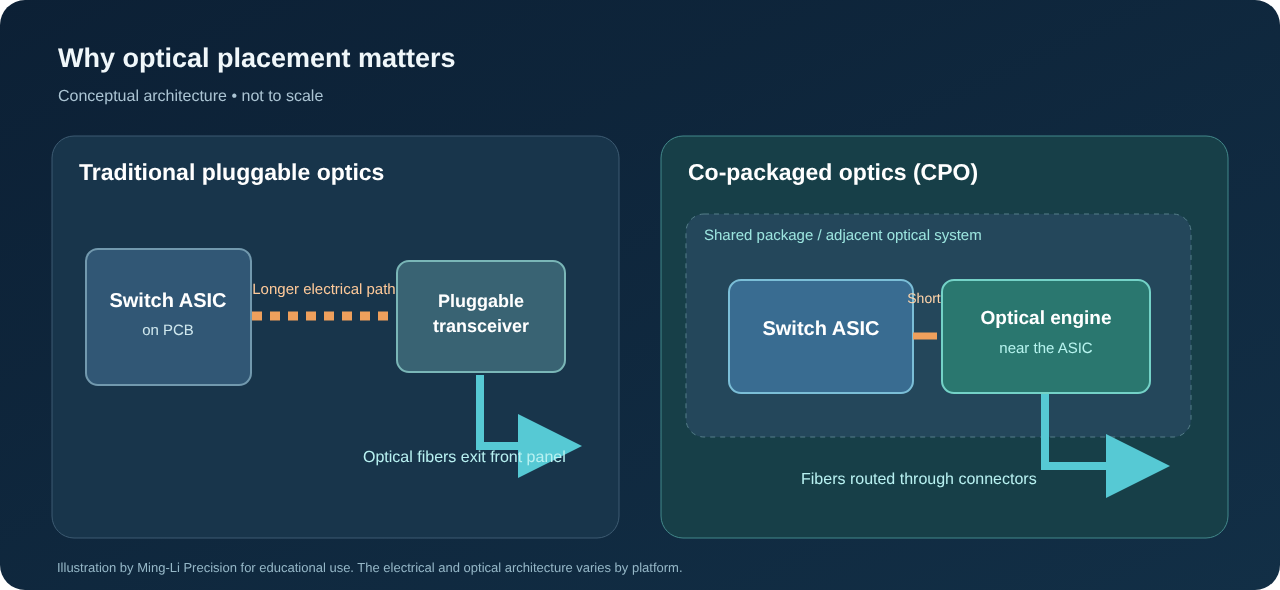
The optical semiconductor and its packaging remain the core of CPO, but the surrounding assembly may also require mechanically precise polymer components. Housings, clips, brackets, fiber-management guides, protective covers and insulating carriers can influence assembly repeatability, mechanical stability, service access and long-term reliability.
Importantly, a molded support is not equivalent to a sub-micron optical alignment element. Glass, silicon, ceramic, precision metal and other technologies may be required for critical optical interfaces. Their use should be determined by the customer’s optical, mechanical and thermal tolerance budget.
Optical interconnect architecture comparison
| Engineering consideration | Conventional pluggable optics | Co-packaged optics (CPO) | Implication for polymer component design |
|---|---|---|---|
| Optical engine location | Removable module at equipment faceplate | At or very near the switch ASIC | More demanding packaging space and thermal integration |
| High-speed electrical path | Longer board-level reach | Significantly shortened near-package link | Small, stable mounting and retention features may matter more |
| Fiber management | Front-panel transceiver connections | Fibers routed from tightly integrated assemblies | Fiber guides, strain relief and service-clearance planning |
| Service model | Module can be replaced independently | System-level approach varies by implementation | Reliable connector retention and assembly access become important |
| Heat environment | Separated from the hottest switch package | Optical structures can be near high-power silicon | Resin selection must reflect actual operating temperatures |
| Qualification | Established pluggable-module ecosystem | Evolving architecture-specific requirements | Application-specific test plan, not generic “CPO approved” claims |
2. Where Advanced Polymer Components Fit in the CPO Ecosystem
Ming-Li focuses on the precision mechanical and insulating structures that surround optical systems, rather than semiconductor fabrication or the design of the optical engines themselves. Potential opportunities include the following categories; their suitability depends on interface drawings, tolerances and system constraints.
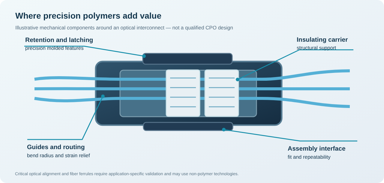
2.1 Fiber-optic connector housings and retention mechanisms
Compact optical interconnects can require intricate housings, latching features, keyed geometry, mounting bosses and insertion stops. For such parts, precision connector injection molding must be assessed for dimensional repeatability, shrinkage, molded-in stress, insertion forces and flash at functional interfaces. A polymer housing may be moldable even when the optical ferrule or alignment block itself requires another manufacturing process.
2.2 Fiber routing, guides and strain-relief components
Dense optical assemblies often need repeatable fiber routing while preserving minimum bend radius and limiting tensile loading. Candidate parts include precision cable guides, routing clips, covers, strain-relief structures and protective carriers. These are mechanical components; optical loss and reliability must be tested in the final assembly by the system owner.
2.3 Optical engine support frames and insulating structures
Depending on the package architecture, support frames, electrical insulation pieces, protective enclosures and mechanical retainers may use specialty engineering polymers. Such parts require careful review of thermal expansion mismatch, creep, outgassing or contamination limits, warpage and assembly preload.
2.4 Insert-molded optical-electronic components
Some components combine metal inserts, pins, bushings, shielding or fastening features with molded polymer. Insert molding can consolidate assembly steps and create robust functional structures. Feasibility depends on insert geometry, retention performance, resin processing conditions, thermal cycles and how the final assembly is verified.
2.5 Precision mold inserts and high-tolerance tooling
Not every customer needs finished injection-molded parts. Optical connector suppliers may also seek precision mold inserts, micro-machined cavities, mold components and tooling support. Ming-Li offers an integrated route from DFM to toolmaking, trial molding and inspection.
Opportunity matrix: application and manufacturing scope
| CPO / photonics application area | Potential polymer or tooling deliverable | Key engineering review | Ming-Li service to evaluate |
|---|---|---|---|
| High-density optical connector | Housing, latch, guide, protective cover | Shrinkage, fit, insertion loads | Precision molding and mold design |
| Fiber management | Clips, routing tray, strain-relief support | Bend radius, creepage, particle generation | Molded component development |
| Optical engine mechanical structure | Frame, retainer, insulating spacer | CTE, thermal distortion, assembly tolerance | High-performance polymer molding |
| Optical module enclosure | Enclosure or mechanically protective cover | Warpage, fastening, temperature | Injection mold and molding |
| Metal/polymer subassembly | Insert-molded terminal or metal-retention part | Insert positioning and mechanical integrity | Insert molding / overmolding |
| Molded microstructure | Fine-feature plastic part | Gate placement, venting, micro-feature replication | Micro molding feasibility study |
| Precision mold supplier | Core, cavity, slide, spare tooling part | Machining accuracy and verification | Ultra-precision moldmaking |
3. Engineering Materials: LCP, PPS, PEEK, PEI and Other High-Performance Polymers
Material selection is one of the first decisions in optical-interconnect mechanical design. A material that looks ideal on a data sheet may behave very differently in a thin-walled part with asymmetrical ribs, fiber-filled flow, complex gates or significant mold-in stress. For CPO polymer engineering, the final grade and its validation matter more than the generic resin family name.
Engineering polymer selection guide
| Polymer family | Potential advantages | Engineering trade-offs to verify | Candidate structural application |
|---|---|---|---|
| LCP (Liquid Crystal Polymer) | High flow in thin sections; potentially strong dimensional stability; high-temperature grades available | Anisotropic shrinkage, weld lines, directional properties and filler orientation | Thin-wall connector housings, small structural supports |
| PPS (Polyphenylene Sulfide) | Thermal and chemical resistance; electrical insulation; filled grades with good stiffness | Brittleness in some formulations, weld-line strength, molding conditions and part warpage | Frames, insulating carriers, dimensionally stable housings |
| PEEK (Polyether Ether Ketone) | Excellent high-temperature and mechanical performance for demanding environments | Higher resin cost, high processing temperature, crystallinity control and tooling requirements | Specialty supports, demanding mechanical insulation parts |
| PEI (Polyetherimide) | Amorphous high-temperature material with potential dimensional benefits | Process temperatures, stress sensitivity and grade-dependent chemical resistance | High-performance electrical or structural components |
| PPA (High-performance Polyamide) | Mechanical strength and connector-grade availability | Moisture absorption, conditioning effects and grade-dependent stability | Connector structures where the environment allows |
| PBT / engineering blends | Established connector-material ecosystem and potentially favorable economics | Heat resistance, hydrolysis and dimensional performance depend heavily on grade | Peripheral housings and cost-sensitive structures |
This table is a material-screening guide, not a claim that any grade is automatically certified for CPO. Flame ratings such as UL 94, CTI values, outgassing limits and performance at final wall thickness must be checked against the specific supplier's grade documentation and the OEM's requirements.
What should be validated before selecting a resin?
Thermal expansion (CTE) and dimensional drift. If a polymer carrier interfaces with glass, ceramic, silicon or metal, different expansion rates can alter mechanical preload or positioning. Evaluate the full stack-up across the defined operating and assembly temperature range—not just room-temperature dimensions.
Mold shrinkage and fiber orientation. Filled engineering polymers may shrink differently along and across flow. The gate scheme, weld lines, processing window, cooling balance and part geometry all affect as-molded and conditioned dimensions.
Creep and stress relaxation. Connector latches and retaining features may remain loaded for years. Static and cyclic loads, thermal exposure and resin grade should be considered when establishing performance requirements.
Cleanliness and particulate control. Loose flash, wear debris, surface contamination and packaging particles can be unacceptable near sensitive optical interfaces. Cleanliness limits should be explicit in the drawing and manufacturing control plan. A low-particle requirement is not the same as a claim of cleanroom-certified production.
Flame retardancy and compliance. Requirements such as UL 94, REACH or RoHS should be defined by part, grade, region and customer specification. The engineering team must confirm document validity rather than assume that a polymer-family label guarantees compliance.
4. Why Precision Mold Design Is Critical for Optical Connector Components
The mold determines far more than the outward shape of a plastic component. For small, highly featured parts, tool design can influence the consistency of mating interfaces, repeatability of clips and alignment supports, local flash, dimensional scatter and automated assembly performance.
Key design-for-manufacture (DFM) topics include:
- Critical-to-quality dimensions (CTQs): identify functional datums, retention surfaces and mating interfaces instead of applying unnecessary tight tolerances everywhere.
- Gate position and fill balance: manage weld lines, fiber orientation and local packing effects that can distort mechanical features.
- Vent design and flash prevention: protect connector faces, thin edges, small slots and moving interfaces.
- Cooling and thermal symmetry: reduce differential shrinkage and warpage of slender supports and frames.
- Mold steel and insert strategy: select machining approaches that support fine details, maintainability and repeatable cavity performance.
- Measurement accessibility: establish how the part will be measured before cutting steel; complex features may need CMM, optical measurement or industrial CT.
- Assembly-ready inspection: test actual mechanical function, not dimensional compliance alone.
Hot runner or cold runner for precision engineering polymers?
| Tooling question | Cold runner | Hot runner |
|---|---|---|
| Initial mold complexity | Often simpler | More integration and control required |
| Runner material consumption | Sprue/runner waste may be significant | May reduce runner waste |
| Thermal control | Generally more straightforward | Requires resin-specific hot-runner compatibility |
| Material sensitivity | Easier to evaluate some sensitive specialty grades | Residence time and degradation risk demand careful review |
| Gating small precision parts | Depends on geometry and runner design | Depends on available nozzle, gate and temperature control |
| Best selection basis | Part size, shot volume, resin and quality target | Same criteria plus economics and processing validation |
There is no universally superior runner choice for LCP, PPS or PEEK. An appropriate quotation compares tool cost, cavity count, gate restrictions, cycle time, part quality, runner waste and production volume under a defined material grade.
5. Ming-Li Precision: Manufacturing Capabilities Relevant to Optical Interconnects
Founded in 1983, Ming-Li Precision Steel Molds Co., Ltd. has built its business around precision mold manufacturing and engineering-plastic injection molding. Its official company profile describes more than 5,000 precision mold projects, YASDA ultra-precision CNC machining, in-house mold development and injection production, micro molding and insert molding, along with an IATF 16949-certified quality management system.
These capabilities are relevant to photonics projects because demanding mechanical components often need to pass through several closely coordinated operations: precision tooling, high-temperature molding, metrology, sample evaluation and ongoing production control.
Manufacturing capability and customer value
| Ming-Li capability | What it supports in a CPO-related project |
|---|---|
| Precision mold design and DFM | Moldability review of dense, small, complex geometry |
| YASDA ultra-precision machining | Fine-feature cores, cavities, inserts and mold components |
| High-temperature polymer molding | Grade-specific processing evaluation for LCP, PPS, PEEK and PEI |
| Micro molding | Small parts and complex micro-features, feasibility dependent |
| Insert molding and overmolding | Mechanical structures combining polymer and embedded metal features |
| Moldflow analysis | Process and warpage risk assessment, where applicable |
| ZEISS metrology, optical inspection and industrial CT | Dimensional checks and internal-feature inspection, per measurement plan |
| IATF 16949 quality system | Structured process management, traceability and quality planning |
| Mold trials and FAI | Early production evidence to refine tooling and part requirements |
Important manufacturing scope: ±1 μm references on Ming-Li’s corporate materials describe particular ultra-precision machining capability, not a blanket ±1 μm tolerance guarantee for molded parts. Achievable molded dimensions depend on geometry, process, material and measurement method, and must be confirmed per RFQ.
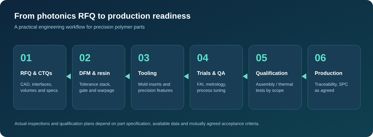
A practical manufacturing workflow
Step 1 — Requirements review. Evaluate 2D/3D CAD, part function, mating geometry, assembly load, resin grade, thermal environment, annual volume, cleanliness and inspection needs.
Step 2 — DFM and polymer selection. Assess wall thickness, draft, undercuts, gate and runner choices, tolerance stack-up and resin processing constraints.
Step 3 — Tooling development. Manufacture precision mold components and evaluate cavity configuration, maintenance and expected shot life.
Step 4 — Mold trials and first-article inspection. Review molded samples, inspect CTQs and document deviations before any agreed tool correction.
Step 5 — Application qualification. Collaborate with the customer on mechanical assembly, thermal cycling, retention, cleanliness and any required optical-system testing. Specialized tests outside the molding supplier’s scope remain the responsibility of the relevant qualified partner.
Step 6 — Controlled production. Implement the agreed control plan, inspection frequency, packaging, lot traceability and change-management procedures.
6. CPO vs. NPO vs. Conventional Optical Modules: Avoiding Procurement Confusion
The optical-connectivity sector uses several related terms. CPO places optical engines in a tightly integrated package-level relationship with the host ASIC. Near-packaged optics (NPO) brings optical functionality close to the switch but may use a more modular arrangement. Pluggable optics typically locates transceivers at the system front panel. The distinctions depend on the platform, and the market is still evolving.
For precision-component sourcing, this means a supplier should first ask where the component sits and what mechanical function it performs, rather than automatically labeling every fiber-related plastic part a “CPO component.” A housing for an MPO/MTP-type connector, for example, is not automatically a qualified CPO optical interface.
7. Technical Checklist: What to Send for a CPO Precision Molding RFQ
Engineering teams can accelerate feasibility assessment with the following information:
| RFQ information | Why it matters |
|---|---|
| 3D CAD (STEP/Parasolid) and controlled 2D drawing | Establishes geometry, datums and tolerance requirements |
| Assembly model / mating components | Reveals mechanical fit, insertion path and stack-up |
| Material grade and supplier | Defines processability, shrinkage and technical properties |
| Operating temperature and thermal profile | Supports CTE, heat aging and material assessment |
| Critical-to-quality features | Focuses tooling and metrology on functional risks |
| Insertion/retention, load and life-cycle requirements | Supports latch and structural integrity review |
| Particulate, cleanliness and packaging limits | Prevents mismatched process-control expectations |
| Expected annual volume and launch plan | Guides cavity count, runner choice and economics |
| Inspection, reporting and traceability requirements | Establishes an achievable quality and quotation scope |
| Optical-system qualification owner | Clarifies responsibility for optical tests beyond molded-part inspection |
No 3D model available? Physical samples and 2D drawings can support an initial discussion, but a reliable tool quote usually requires a controlled 3D definition and a confirmed material specification. Reverse engineering can be evaluated as a separate scope where samples, access and intellectual-property rights allow.
8. Frequently Asked Questions
Can Ming-Li manufacture plastic parts for CPO applications?
Ming-Li can review drawings and evaluate manufacturing feasibility for CPO-related mechanical and insulating polymer components, including connector housings, retaining structures, fiber-management parts, precision tooling and insert-molded assemblies. Application suitability, tolerances and qualification must be reviewed individually. This is not a claim of existing CPO platform approval.
Does CPO use only plastic components?
No. CPO combines semiconductor ASICs, photonic chips, optical engines, substrates, fiber arrays, connectors, heat-management components and other technologies. Polymers support selected mechanical, retention and insulating functions; they do not replace silicon photonics or precision optical interfaces.
Which is better for CPO structural components: LCP, PPS or PEEK?
There is no single best resin. LCP can be attractive for thin-wall connector geometry, PPS for certain heat-resistant insulating structures, and PEEK for demanding high-temperature applications. Actual grade, dimensions, loads, operating environment, cleanliness and economics determine the final choice.
Can injection molding achieve sub-micron optical alignment tolerances?
Do not assume so. Sub-micron optical alignment is a specialized system-level requirement often handled with glass, silicon, ceramic, active alignment or other techniques. An injection-molded housing or support must be evaluated separately for its mechanical tolerance requirements.
Can Ming-Li support low-volume prototypes and subsequent mass production?
Projects can be reviewed across prototype and production stages, including DFM, tooling, trials, inspection and manufacturing. Cavity count, expected lead time and cost depend on complexity, selected resin, approval scope and forecast volume.
Does Ming-Li offer insert molding for optical-electronic assemblies?
Yes, insert molding and overmolding are established Ming-Li manufacturing capabilities. For any optical-electronic subassembly, insert retention, insulation, thermal compatibility, geometry and qualification requirements must be validated against the specific design.
Is Ming-Li a certified CPO optics manufacturer?
Ming-Li’s existing certification is IATF 16949 for its manufacturing quality system. This is not an optical-platform certification and does not indicate qualification by a specific CPO system provider. The company invites customer drawings for project-specific feasibility and supplier qualification.
What is the fastest way to receive a meaningful quotation?
Provide final 2D/3D data, assembly interfaces, material grade, drawings with critical dimensions, expected annual quantity, target launch date and relevant cleanliness and inspection requirements. Include whether the inquiry covers only tooling, molded components, or assembled parts.
9. Partner with Ming-Li for Next-Generation Optical Interconnect Manufacturing
Advanced optical communications demand more than miniaturization. They require careful consideration of thermal behavior, high-performance polymer processing, mechanical alignment support, precision tooling and quality documentation. The most successful programs define what the polymer component must do, select a suitable manufacturing route, then validate the final assembly against the real operating environment.
Ming-Li Precision welcomes inquiries from photonics companies, optical-connector manufacturers, network equipment suppliers, R&D teams and contract manufacturers seeking a Taiwan-based precision polymer engineering and injection mold partner.
Discuss your next CPO-related mechanical component, silicon photonics structural part or optical connector molding project with our engineering team.
Ming-Li Precision Steel Molds Co., Ltd.
No. 13, 36 Rd., Taichung Industrial Park, Taichung 40768, Taiwan
Email: karl@mingli-molds.com.tw
Telephone: +886-4-2359-9288
Company profile: Ming-Li Precision
Precision molding services: Engineering plastic molding and insert molding
Contact engineering: Request a technical review
Sources and technical reading
- NVIDIA — Spectrum-X Ethernet Photonics technical introduction — discussion of CPO architecture, detachable fiber connectors and deployment considerations.
- Corning — Optical connectivity and CPO ecosystem at OFC 2026 — fiber arrays, optical management and system integration.
- Ming-Li — Company profile — company history, quality system and manufacturing capabilities.
- Ming-Li — Precision molding solutions — manufacturing technologies and component categories.
Editorial note: Technical diagrams are conceptual. Material properties, optical performance, achievable tolerances, CPO qualification and regulatory conformity must be verified for each project. The article describes available manufacturing capabilities and prospective application areas, not completed CPO production case studies.