
Bearing Insert Molding & Bearing Overmolding Solutions
Ming-Li Precision integrates bearings directly into injection-molded plastic components for pulleys, idlers, guide rollers, tensioners, gears, and other rotating mechanisms—supporting customers from DFM and mold engineering through validation, automation, and mass production.
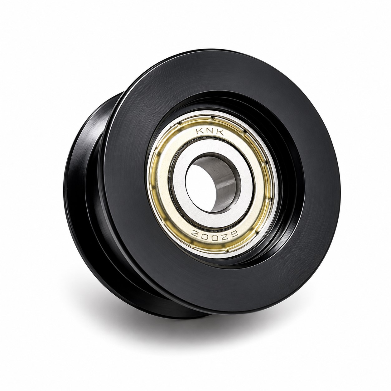 Integrated bearing and molded pulley produced through precision bearing overmolding.
Why Integrate the Bearing During Injection Molding?
In pulleys, idlers, guide rollers, tensioners, gears, and other rotating components, the interface between the bearing and the molded plastic body directly affects concentricity, rotational resistance, noise, durability, and long-term reliability.
Conventional production normally molds the plastic component first and installs the bearing later by press fitting, riveting, heat staking, adhesive bonding, or another secondary process. These extra operations can introduce bearing misalignment, plastic-housing deformation, insufficient retention force, tolerance accumulation, and additional assembly cost.
The bearing is located in the mold and integrated with the plastic body during the molding cycle.
Tooling datums and controlled molding conditions reduce variation associated with separate bearing installation.
The process can be developed for manual loading, robotic insert handling, presence detection, and automated inspection.
What Is Bearing Insert Molding?
Bearing insert molding is an injection molding process in which a metal bearing is positioned inside the mold before plastic injection. Molten resin flows around the bearing or selected areas of its outer ring. After cooling, the bearing becomes mechanically integrated with the molded plastic component.
Typical applications
- Pulleys and idler wheels
- Belt tensioners and guide rollers
- Plastic gears with integrated bearings
- Conveyor components
- Automotive rotating components
- Industrial, medical, and electromechanical mechanisms
Primary manufacturing benefit
Bearing insert molding can eliminate a separate bearing-installation operation and reduce assembly variation. The tooling, bearing-locating structure, resin, gate position, and molding window must be engineered as one complete system.
What Is Bearing Overmolding?
Bearing overmolding is a specialized form of insert molding in which plastic is molded directly around the bearing outer ring or around a defined retention area. The overmolded geometry can provide mechanical retention, structural integration, load distribution, vibration resistance, and lower total assembly cost.
In industrial usage, “bearing insert molding” and “bearing overmolding” are sometimes used interchangeably. Bearing overmolding generally places more emphasis on the amount of resin surrounding the bearing and the mechanical locking strategy between the bearing and molded body.
| Process | Main characteristic | Typical applications | Primary engineering focus |
|---|---|---|---|
| Bearing insert molding | The bearing is positioned as a metal insert before plastic injection. | Bearing housings, gears, rollers, pulleys, and mechanical components. | Accurate insert positioning and repeatable integration. |
| Bearing overmolding | Plastic surrounds the bearing outer ring or a defined retention area. | Idler pulleys, belt tensioners, guide wheels, and high-load rotating parts. | Retention geometry, shrinkage stress, sealing, and rotational performance. |
Key Technical Challenges in Bearing Insert Molding
A bearing is a precision mechanical component. Its performance can be affected by injection pressure, mold and melt temperature, cooling shrinkage, tooling accuracy, and the direction of resin flow. Successful production requires control of the following five areas.
Bearing Positioning and Concentricity
The bearing must remain accurately located during mold closing, injection, packing, and cooling. Incorrect support can cause displacement, inclination, uneven wall thickness, radial or axial runout, and misalignment between the bearing and pulley.
Ming-Li designs locating and supporting features around the bearing inner diameter, outer diameter, end face, and final product datums.
Preventing Resin Leakage
Molten resin can enter the bearing through shield, seal, outer-ring, or end-face clearances. This may cause bearing seizure, increased torque, grease contamination, abnormal noise, reduced life, or unstable rotation.
Precision shut-off surfaces and bearing-protection features must prevent flash and resin penetration without damaging the bearing.
Controlling Shrinkage Pressure
As resin cools, shrinkage can create radial pressure on the bearing outer ring. Excessive compression may deform the outer ring, change internal clearance, increase rotational resistance, or reduce bearing life.
Development considers resin shrinkage, fiber content, temperatures, packing pressure, overmolding thickness, cooling balance, outer-ring strength, and locking geometry.
Injection Pressure and Bearing Movement
Unbalanced resin flow can push the bearing away from its intended position. Moldflow analysis helps evaluate flow direction, pressure distribution, weld lines, air traps, filling balance, fiber orientation, and potential insert movement.
Gate position and flow path are optimized to reduce one-sided loading around the bearing.
Mechanical Retention Design
The bearing must remain securely fixed throughout the product service life. Retention may use radial interference, axial plastic locking, flanges, grooves, undercuts, steps, selective encapsulation, or a combination of mechanical locking and shrink-fit retention.
The correct approach depends on load, speed, temperature, vibration, resin type, and product geometry.
Material Selection for Bearing Overmolding
The resin must be selected according to the mechanical, thermal, dimensional, and environmental requirements of the final component.
Selection criteria
- Dimensional stability and mold shrinkage
- Creep, impact, and wear resistance
- Operating temperature and chemical exposure
- Moisture absorption
- Rotational load and long-term bearing retention
Fiber-reinforced materials
Glass-fiber-reinforced resins can provide higher stiffness and improved dimensional stability. They may also create higher shrinkage stress and more complex fiber-orientation effects around the bearing, so tooling and process conditions must be developed accordingly.
Bearing Overmolding Case: Integrated Pulley / Idler Wheel
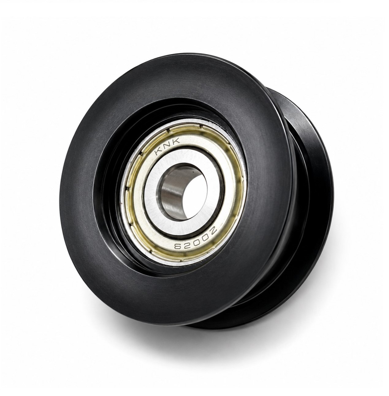
One practical application developed by Ming-Li is an overmolded pulley or idler wheel with an integrated metal ball bearing. The bearing is positioned directly in the injection mold, and black engineering plastic is molded around it to form the complete pulley structure.
Integrated construction
The bearing, running surface, groove profile, and retention structure are combined in one molded component.
Reduced secondary assembly
The design avoids a separate post-molding bearing press-fit operation and its associated tolerance stack.
Stable manufacturing process
The mold, bearing, plastic material, cooling, and inspection plan are developed together for repeatable production.
Dimensional and Functional Inspection
For bearing insert-molded components, dimensional inspection alone may not be sufficient. Functional performance must also be evaluated.
Possible inspection items
- Bearing position and concentricity
- Radial and axial runout
- Overall diameter and groove profile
- Bearing retention force
- Rotational torque and deformation
- Flash, resin penetration, and surface quality
Ming-Li metrology support
- Coordinate measuring machines
- Optical measuring systems
- ZEISS CT scanning and 3D scanning
- First Article Inspection
- SPC and CPK analysis
CT scanning is especially useful for evaluating hidden internal structures, bearing position, plastic distribution, voids, and internal defects without destroying the part.
Mold Design Considerations for Bearing Overmolding
A successful bearing overmolding tool must balance precision, bearing protection, manufacturability, and production efficiency.
Loading direction
The bearing must be easy to load while remaining securely positioned before mold closing.
Orientation control
The mold and loading fixture should prevent the bearing from being installed in the wrong direction.
Insert detection
Sensors or vision systems can confirm bearing presence and correct positioning before injection.
Shut-off accuracy
The mold must seal around the bearing without damaging its shield, seal, or outer ring.
Gate and cooling design
Balanced filling and cooling reduce one-sided pressure, warpage, uneven shrinkage, and bearing displacement.
Ejection design
The finished part must be ejected without transferring excessive force through the bearing.
Manual and Automated Bearing Loading
The correct loading concept depends on production volume, cavity count, bearing orientation, cycle-time targets, and inspection requirements.
Manual loading
Suitable for prototype production, low-volume programs, engineering validation, complex orientation, and early-stage product development.
Automated loading
Suitable for high-volume production, multi-cavity molds, short cycles, consistent orientation, reduced labor dependency, and 100% insert-presence verification.
When required, Ming-Li can integrate robotic bearing loading, insert detection, molded-part removal, and automated inspection into the production system.
Why Choose Ming-Li Precision for Bearing Insert Molding?
Ming-Li combines mold engineering, precision machining, injection molding, metrology, and automation under one manufacturing platform. Because we understand both mold manufacturing and molding, we can evaluate the complete process—from bearing positioning and tooling design to molding parameters, inspection, and automation.
Engineering
- DFM and tolerance analysis
- Moldflow analysis
- Bearing-retention concept development
- Material-selection support
Manufacturing
- Precision mold manufacturing
- Bearing insert molding
- Bearing overmolding
- High-performance engineering plastics
Validation and scale-up
- Dimensional and CT inspection
- Process optimization
- Automated insert loading
- Prototype-to-mass-production support
Bearing Insert Molding Development Process
- Product and bearing specification review
- DFM and tolerance analysis
- Bearing-retention concept development
- Moldflow analysis
- Mold and bearing-positioning design
- Precision mold manufacturing
- Initial mold trial
- Dimensional and functional inspection
- Process optimization
- Automation evaluation
- Mass-production validation
This integrated approach helps reduce development risk and ensures that the mold, bearing, material, and molding process are designed as one complete system.
Frequently Asked Questions About Bearing Insert Molding
What is the difference between bearing insert molding and bearing overmolding?
Bearing insert molding describes the broader process of placing a bearing into the mold before injection. Bearing overmolding usually describes a design in which resin surrounds the bearing outer ring or a defined retention area to create a more integrated mechanical structure.
Can injection pressure move or damage the bearing?
Yes, if the locating structure, gate position, shut-off surfaces, or molding conditions are not properly designed. The process must control one-sided resin pressure, clamping force on the bearing, and cooling shrinkage.
How is resin prevented from entering the bearing?
Precision mold shut-offs and bearing-protection features seal critical areas around the shield, seal, outer ring, and end face. The design must prevent flash and resin penetration without crushing or deforming the bearing.
Which plastics can be used for bearing overmolding?
Common options include PA6, PA66, glass-fiber-reinforced nylon, POM, PBT, PPS, PPA, PEI, PEEK, and other engineering polymers. Selection depends on shrinkage, load, temperature, moisture, wear, chemical exposure, and dimensional requirements.
Can bearing loading be automated?
Yes. High-volume production can integrate robotic loading, orientation control, insert-presence detection, part removal, and automated inspection. Manual loading remains practical for prototypes and lower-volume programs.
Discuss Your Bearing Insert Molding Project
Send Ming-Li your 2D drawing, 3D model, bearing specification, resin requirement, annual volume, and critical dimensional or functional requirements for an engineering review.
Related resources: Precision insert molding and overmolding manufacturer · Ming-Li technical articles